


Designing for Safety: Busbar Stress Analysis in New Energy Systems
Busbar Stress Analysis and Safety Design Principles
— The Structural Core for Reliable Operation in New Energy and Power Distribution Systems
1. What is Busbar Stress Analysis?
Busbar stress analysis refers to the evaluation of mechanical, thermal, and electromagnetic stresses acting on a busbar under various operating conditions. It ensures that the busbar maintains structural integrity—without deformation, loosening, or damage—throughout long-term operation. In essence, it is a key design process to verify the mechanical strength, safety margin, and structural reliability of a busbar before it is put into service.
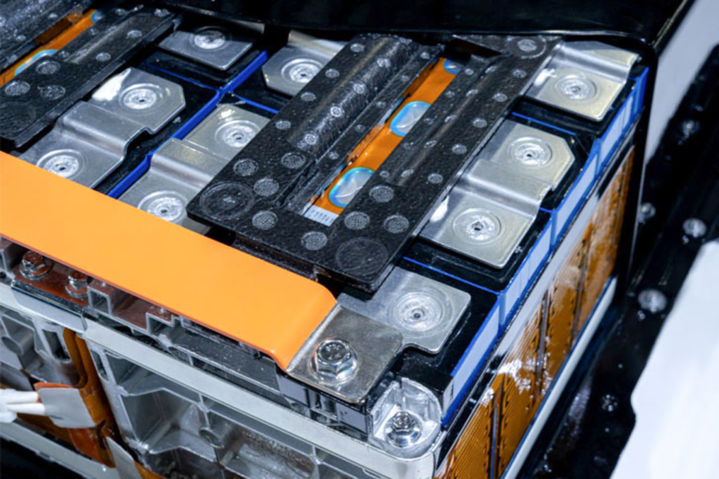
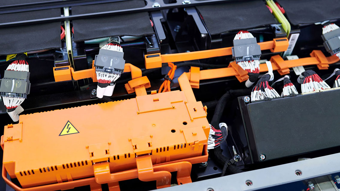
In new energy drive systems, energy storage stations, and high- and low-voltage distribution equipment, the copper busbar is a key component for current transmission and power distribution. Beyond conducting large currents, it also serves critical functions in mechanical support, thermal conduction, and insulation.
With the continuous rise in voltage and current levels, and as system layouts become increasingly compact, busbars are now subject to significantly higher mechanical, thermal, and electromagnetic stresses during operation. Improper stress design can directly compromise system safety and reliability.
Therefore, conducting a scientific analysis of busbar stress and establishing robust safety design strategies are essential steps in both new energy busbar manufacturing and power distribution system engineering.
2. Major Types and Characteristics of Busbar Stress
During manufacturing, assembly, and operation, electrical busbars are simultaneously exposed to multiple sources of stress, primarily including:
2.1 Mechanical Installation Stress
Improper assembly tolerances, support positions, or fastening methods can introduce residual stress during installation.
Although not immediately visible, these stresses may accumulate over time under heat cycling or vibration, causing permanent deformation, insulation cracking, or loose connections.
In EV drive systems and power distribution cabinets, such stresses are often hidden causes of early failures.
2.2 Electrodynamic Stress
During short-circuit or surge events, transient currents several times the rated value generate strong electromagnetic forces between busbars.
These forces—often reaching several kilonewtons or more—can cause busbar displacement, bending, or even phase-to-phase collision if supports are inadequately designed, leading to insulation breakdown or short-circuit faults.
2.3 Thermal Stress
Copper has a relatively high coefficient of thermal expansion (≈17×10⁻⁶/K). During long-term operation or frequent start–stop cycles, copper busbars repeatedly expand and contract.
If constrained by bolts or mounting structures, thermal expansion stress accumulates, potentially leading to insulation aging, joint loosening, or structural cracking.
In EVs, energy storage systems, and high-voltage panels, uncompensated thermal stress is a frequent reliability challenge.
2.4 Vibration and External Load Stress
In high-vibration applications—such as electric vehicles or wind power converters—busbars endure long-term cyclic mechanical loads.
These lead to micro-motion wear, fatigue accumulation, and increased contact resistance, all of which reduce system reliability over time.
3. Methods for Busbar Stress Analysis
Accurate stress evaluation is the foundation of busbar design and must integrate simulation, experimental validation, and engineering experience.
3.1 Finite Element Analysis (FEA)
By combining 3D modeling and multiphysics simulation, engineers can analyze the coupled electromagnetic, thermal, and mechanical behavior of electrical busbars.
FEA identifies stress concentration areas, maximum displacement zones, and fatigue-prone regions, providing essential data for structural optimization.
3.2 Multi-Field Experimental Verification
Through short-circuit impact tests, thermal cycling, and vibration testing, the deformation, contact stability, and temperature rise of copper busbars can be evaluated under extreme conditions.
These tests reflect real operational stress states and are critical for product validation and safety certification.
3.3 Strain and Fatigue Monitoring
By placing strain gauges at key connection points, engineers can monitor assembly stress and operational strain in real time, assessing fatigue life and structural safety margins—particularly for battery packs and high-voltage switchgear in long-term operation.
4. Safety Design Principles and Engineering Practices
In both new energy and power distribution applications, power busbar safety design must comprehensively address structure, materials, process, and installation.
4.1 Structural Design Optimization
-
Arrange support points and spacing to prevent excessive deflection.
-
Maintain a minimum bending radius of three times the thickness to reduce stress concentration.
-
Use multi-layer configurations to balance magnetic and thermal forces.
-
Incorporate sliding supports or expansion joints in long runs to release thermal stress.
4.2 Material Selection and Surface Treatment
-
Choose T2 or C1100 high-conductivity copper to balance electrical and mechanical performance.
-
Apply tin or nickel plating to minimize contact resistance and prevent oxidation.
-
Use high-temperature insulation materials such as PI, PPS+GF, or PVC dip coating to ensure insulation integrity under deformation and heat.
4.3 Process and Assembly Control
-
Manage bending stress and annealing processes to reduce residual stress.
-
Avoid forced assembly—ensure natural alignment and stress-free installation.
-
Use torque-controlled fasteners to maintain proper contact pressure and prevent insulation damage.
4.4 Testing and Monitoring
-
Perform deformation, temperature rise, dielectric, and short-circuit tests before product delivery.
-
Integrate temperature or strain sensors at critical nodes for ongoing performance monitoring and predictive maintenance.
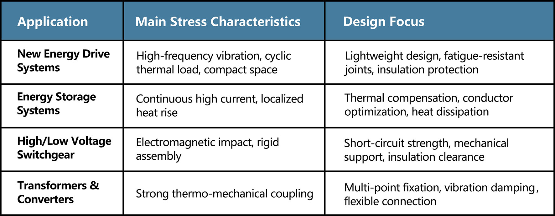
5. Design Focus Across Different Applications
6. Future Trends and Innovation Directions
Digital Simulation and Validation
Digital twin technology enables real-time monitoring and virtual optimization of coupled thermal–mechanical–electrical performance, improving design accuracy and validation efficiency.
Lightweight Composite Structures
Copper–aluminium composite and carbon-fiber-reinforced power busbars balance conductivity, strength, and weight, supporting next-generation electrification needs.
Automated Assembly and Torque Control
Robotic installation with automated torque management ensures consistent assembly stress and higher process repeatability.
High-Reliability Integrated Insulation Technology
Overmolding and compression molding processes enhance both insulation strength and mechanical vibration resistance, ensuring long-term operational reliability.
Conclusion
Busbar stress analysis and safety design form the foundation for the long-term reliability of new energy and power distribution systems.
From material selection to structural optimization, and from manufacturing control to assembly precision, every stage influences mechanical safety and electrical stability.
Only through a thorough understanding of busbar stress mechanisms—such as vibration load, thermal cycling, and electrodynamic impact—and by clearly defining safety boundaries like current-carrying capacity and insulation limits,
can we truly achieve efficient and secure power transmission within modern energy systems.